Tylko po angielsku, ale może się przyda. Roboty jest.
Intake Manifold Replacement
Removal Procedure
1. Open the hood.
2. Disconnect the battery negative cable. Refer to Battery Negative Cable Disconnection and Connection .
3. Drain the cooling system. Refer to Cooling System Draining and Filling .
4. Remove the exhaust gas recirculation valve cooler. Refer to Exhaust Gas Recirculation Valve Cooler Replacement .
5. Remove the positive crankcase ventilation tube. Refer to Positive Crankcase Ventilation Tube Replacement .
2191194
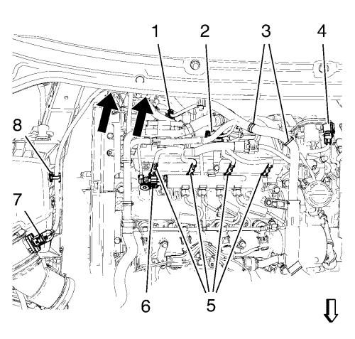
6. Disconnect the wiring harness plugs:
• from the air mess sensor (7).
• from the 4 glow plugs (5).
• from the fuel rail (6).
• from the throttle body (4).
• from the manifold absolute pressure sensor (2).
• from the fuel injection pump (1).
7. Disconnect the wiring harness retainer clips:
• from the air filter assembly (8).
• from the wiring harness bracket (3).
• from the fuel feed hose protector (see arrows in picture).
8. Remove the positive crankcase ventilation oil separator. Refer to Positive Crankcase Ventilation Oil Separator Replacement .
9. Raise and support the vehicle. Refer to Lifting and Jacking the Vehicle .
2018987
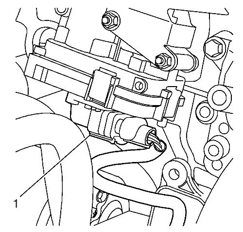
10. Disconnect the wiring harness plug (1) from the intake manifold actuator.
11. Lower the vehicle. Refer to Lifting and Jacking the Vehicle .
12. Remove the fuel injection pump. Refer to Fuel Injection Pump Replacement .
2018988
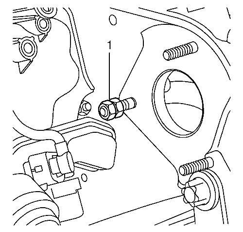
13. Remove the fuel injection pump stud (1), use 2 nuts to counter hold.
2191197
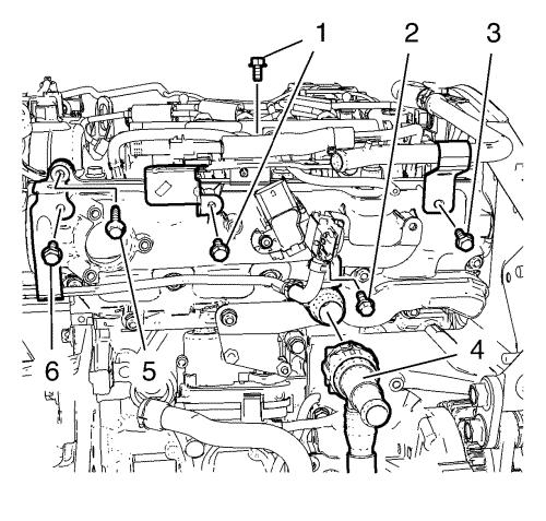
14. Remove the 2 wiring harness bracket bolts (1).
15. Remove the exhaust pressure sensor bracket bolt (2).
16. Remove the positive crankcase ventilation tube bolt (3).
17. Place a drain tray underneath.
18. Remove the water outlet house (4) and hang aside.
19. Remove the intake manifold bracket bolt (5).
20. Remove the exhaust pressure sensor pipe bolt (6).
2191203
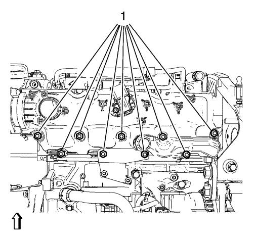
21. Remove the 9 intake manifold nuts (1).
22. Remove the intake manifold.
Installation Procedure
1. Clean the sealing surfaces.
2. Install a NEW intake manifold gasket.
2191203
3. Install the intake manifold.
Caution: Refer to Fastener Caution .
4. Install the 9 intake manifold nuts (1) and tighten to 25 N·m (18 lb ft) .
2191197
5. Install the wiring harness bracket bolts (1).
6. Install the exhaust pressure sensor bracket bolt (2).
7. Install the positive crankcase ventilation tube bolt (3).
8. Install the water outlet house (4).
9. Install the intake manifold bracket bolt (5).
10. Install the exhaust pressure sensor pipe bolt (6).
2018988
11. Install the fuel injection pump stud (1), use 2 nuts to counter hold.
12. Install the fuel injection pump. Refer to Fuel Injection Pump Replacement .
13. Raise the vehicle. Refer to Lifting and Jacking the Vehicle .
2018987
14. Connect the wiring harness plug (1) to the intake manifold actuator.
15. Install the positive crankcase ventilation oil separator. Refer to Positive Crankcase Ventilation Oil Separator Replacement .
2191194
16. Connect the wiring harness plugs:
• to the air mess sensor (7).
• to the 4 glow plugs (5).
• to the fuel rail (6).
• to the throttle body (4).
• to the manifold absolute pressure sensor (2).
• to the fuel injection pump (1).
17. Connect the wiring harness retainer clips:
• to the air filter assemble (8).
• to the wiring harness bracket (3).
• to the fuel feed hose protector (see arrows in picture).
18. Install the positive crankcase ventilation tube. Refer to Positive Crankcase Ventilation Tube Replacement .
19. Install the exhaust gas recirculation valve cooler. Refer to Exhaust Gas Recirculation Valve Cooler Replacement .
20. Connect the battery negative cable. Refer to Battery Negative Cable Disconnection and Connection .
21. Fill the cooling system. Refer to Cooling System Draining and Filling .
22. Close the hood.
Engine > Engine mechanics - 2.0L Diesel (LCD, LBS, LBX, LBY) > Repair Instructions > Inlet Manifold Replacement

 Zobacz nasz portal klubowy ---------------
 Polub naszą stronę na Facebooku ---------------

